
CAN OSI Layer 1
HS-CAN, CAN PN, CAN FD, CAN FD SIC, CAN XL
We offer:
Conformance Test of your Transceivers from CAN High-Speed to CAN XL
ISO 16845-2 is a standardised test specification for testing CAN transceiver implementations. The methods described therein can be used to check the compliance of these implementations with the requirements defined in ISO 11898-1. The tests are divided into different categories. The categorisation is based on the functionalities supported by a transceiver. For example:
- bus wake-up Funktionalität
- selektiver wake-up Funktionalität
- signal improvement capability (SIC)
- fast mode Funktionalität
To ensure that you are on the safe side when using your transceiver, we offer conformity tests for all variants.
Conformance Tests of your CAN High-Speed Transceiver with Selective Wake-up Functions
The selective wake-up function is applied for partial networking to save energy and reduce CO2 emissions.
Partial networking is a method intended to make it possible for a node or for a cluster to be woken individually by means of dedicated and predefined CAN messages instead of being woken by any CAN message as defined in ISO 11898-2 for conventional CAN High-Speed Transceivers.
Since the beginning of 2010 an international working group called SWITCH (Selective Wake-up and Interoperable Transceiver in CAN High-Speed) managed by C&S Group, has been working to make partial networking for CAN bus systems an environmental and commercial success. The documents specified in the framework of this group are currently in the ISO process.
To ensure that you are on the safe side when using your transceiver with selective wake-up functionality, we offer the following tests:
- The ISO 16845-2 which defines the conformance tests for the ISO 11898-2.
- Single device and system tests according to the OEM hardware requirements for partial networking.
We offer:
Interoperability test of your Transceivers from CAN High-Speed to CAN XL
The interoperability test specification was defined based on the requirements of car manufacturers and in collaboration with semiconductor manufacturers. The interoperability tests supplement the test cases of ISO 16845-2. These tests cover the same groups as the conformance tests.
The latest version of the ‘Interoperability Test Specification for High-Speed CAN Transceivers or Equivalent Devices‘ is available to download here:
Do you want to test with us?
Then we need your support so that we can adapt your transceiver smoothly to our test system. We have compiled a document for you, where you can check the relevant requirements.
C&S publications about CAN / CAN-FD Interoperability test
At the 16th international CAN Conference (iCC), in Nuremberg, our employee Christoph Wosnitza gave a presentation on March 7, 2017: Interoperability challenges for CAN-FD/PN Transceivers:Lessons learned from CAN High Speed Interoperability Tests.
Find below a C&S publication about CAN / CAN-FD Interoperability test. If you want more information please send us a mail or give us a phone.
The principle of CAN / CAN-FD Transceiver Testing
CAN Physical Layer Conformance Testing intends to ensure the correct interoperation of CAN transceivers in complex CAN networks that use devices from different suppliers.
After having addressed CAN-FD conformance testing in the new international standards, ISO 16845 1 and ISO 16845 2; requirements from OEMs and silicon vendors were collected and aligned, and test cases have been drafted and specified to enable interoperability of CAN-FD transceivers in a multi-vendor environment. The first release of the Interoperability test specification for high speed CAN transceiver or equivalent devices was published in 2016.
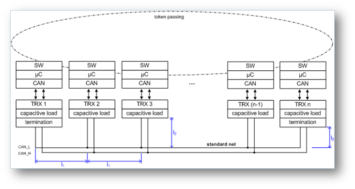
That is one reason why we test CAN transceivers in a so-called standard networks whose structure is defined exactly in the interoperability test specifications. The tests will be performed within the reference environment using predefined settings to ensure a high level of repeatability and comparability of the test results. A data sheet check according to ISO 16845-2 as a static test plan complements the interoperability test.
We test the conformance of the transceiver which reflects its future application conditions.
Test conditions were derived by an international group of automotive OEMs and semiconductor suppliers, the GIFT/ICT group.
The GIFT (Generalized Interoperable Fault Tolerant CAN Transceiver) / ICT (International Transceiver Conformance Test) working group was formed in 1999 and managed by C&S Group in order to establish vendor-independent specifications for the properties of CAN transceivers and specifications for their conformance tests. Its first aim was the draft and creation of a specification of a CAN transceiver module in such a way, that the devices are more flexible for different manufacturers.
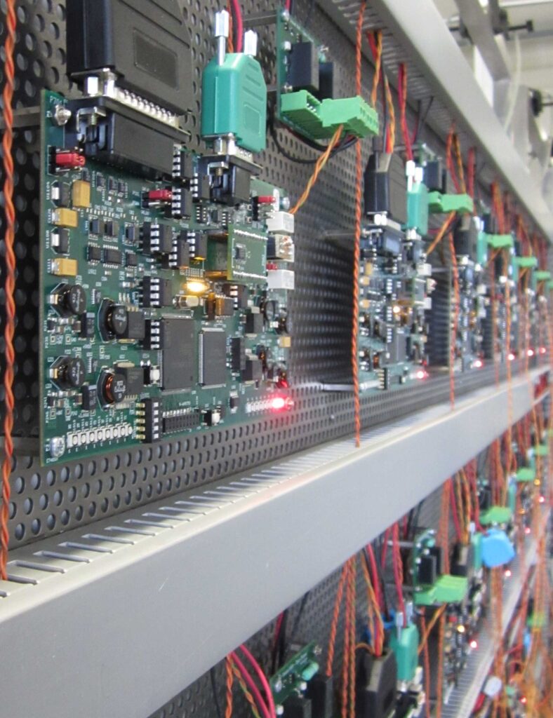
The test systems
The test systems consist of a well-defined standardized network (Standard Net), where the ECUs communicate under various system conditions. A supervisor software controls the system and test sequences. CAN communication is supervised and controlled by calibrated measurement equipment.
The Standard Net consists of a fixed number of identical node, equipped with devices under ‘test only’, or in a given combination with other devices. The devices under ‘test’ have to operate in both “Homogeneous” and “Heterogeneous” networks.
The behavior of a transceiver can be represented by an asynchronous state machine. The transitions, from one state to another, represent reactions to certain events. The dynamic test plan is defined supporting three different data bit rates (500 kbit/s, 2 Mbit/s and 5 Mbit/s) while the arbitration phase is always running with 500 kbit/s. Single test cases are gathered within seven main test cases with different test flows between all possible combinations of normal mode and low power mode. These tests verify the proper behavior under different conditions like:
Within each test flow, eight different failures will be applied:
The interoperability test specification defines nearly 60 thousand single test cases. The correct behavior of the implementation under test will be verified between two and four times per test flow. This results in more than 190 thousand checks per test where the high speed CAN transceiver has to behave correctly.
During the tests the behavior of your CAN transceiver as well as the entire network is compared with the expected behaviors.
The test data – including raw data – are stored for later analysis and to make the test reproducible. The processed data are given to you with your test report.